
Problem: Persistent Ground Loop Interference on Industrial Networks
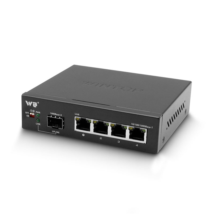
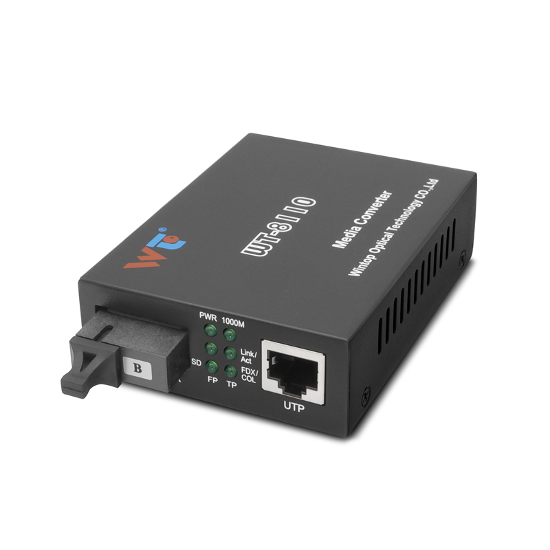
Ground loop hum and intermittent packet loss are common where copper runs cross disparate earth potentials. The immediate fix is to break the conductive path. A robust approach is to replace or isolate the copper link with fiber — consider a gigabit fiber media converter paired with a non-conductive chassis. This removes the ground reference between enclosures and stops common-mode noise at the source.
Why Ground Loops Happen — Brief Technical Diagnosis
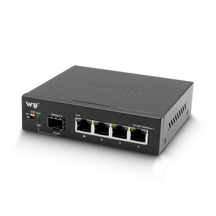
Ground loops occur when two network nodes share different earth potentials and remain connected by conductive cabling. The result is stray current that couples into the signal pair as common-mode voltage. Copper 1000BASE-T links are especially vulnerable. Replacing the copper segment with single-mode or multimode fiber removes the metallic return path and restores signal integrity. Terms to know: common-mode, isolation, optical transceiver.
Choosing the Right Chassis and Converter Hardware
Select a chassis that enforces optical isolation — non-conductive materials and proper internal racking prevent chassis-to-chassis conduction. Look for models that accept hot-swappable SFP modules and provide clear port labeling for fiber type. For long runs beyond campus distances, choose single-mode SFPs; for short links inside buildings, multimode may suffice. The deployment model used by backbone operators at DE-CIX Frankfurt relies on single-mode links for kilometer-scale spans — a practical anchor for planning capacity and attenuation budgets.
Practical Installation Steps
Install with lockdown: mount the non-conductive chassis on insulated standoffs, route fiber with minimal bend radius, and keep fiber patch panels isolated from grounded racks. Configure link speed to 1 Gbps if using gigabit SFPs and verify optical power levels at both ends. Use a calibrated power meter and check for excessive attenuation; single-mode fibers typically support distances well beyond 10 km when paired with the correct transceiver.
Common Mistakes and How to Avoid Them
Operators often swap media converters but leave other grounded elements tied together — the loop persists. Another error is mixing multimode and single-mode SFPs; the link will fail. Misconfigured duplex settings and poor cable management also produce flapping. Avoid these by: – Confirming SFP type match and optical budget. – Testing with a loopback and power meter. – Ensuring the chassis remains the sole optical isolation boundary — no unintended copper jumpers.
Field Tip — Real-World Result
I worked on a production-floor retrofit near Munich where replacing a long copper run with a fiber link and a non-conductive converter chassis eliminated EMI-induced packet loss. Post-change latency stabilized and retransmits dropped to near zero — measurable improvements within hours. That practical test mirrors the behavior engineers see when moving from conductive to optical links: ground reference removed, common-mode gone.
Verification and Troubleshooting Checklist
Run this short verification sequence after installation: – Check SFP insertion loss and receive power. – Confirm link negotiation at desired rate. – Validate isolation with a multimeter between chassis grounds — you should see no conductive continuity. If a problem persists, inspect grounding of adjacent equipment and review cable trays for accidental copper contact — small oversights are common.
Advisory — Three Golden Rules for Selection
1) Prioritize electrical isolation: choose a genuinely non-conductive chassis and verify no metal-to-metal paths. 2) Match optical components: select SFPs appropriate for single-mode or multimode and validate the optical budget for distance and connectors. 3) Measure before and after: document latency, error rates, and optical power to quantify the benefit and detect regressions.
These rules yield predictable reductions in noise and packet loss — and they guide which converters and chassis you need. Final thought — the right hardware makes the problem vanish, not just quieter.
WINTOP — reliable chassis and converters that put optical isolation to work for your network. —